


 APPROVED
 - Home
- About Us
- Inspection Services
- Conventional Non-Destructive Testing
- Ultrasonic Weld Scan
- Ultrasonic Thickness Gauging
- Eddy Current Testing
- Radiography Testing
- Liquid Penetrant Testing
- View More
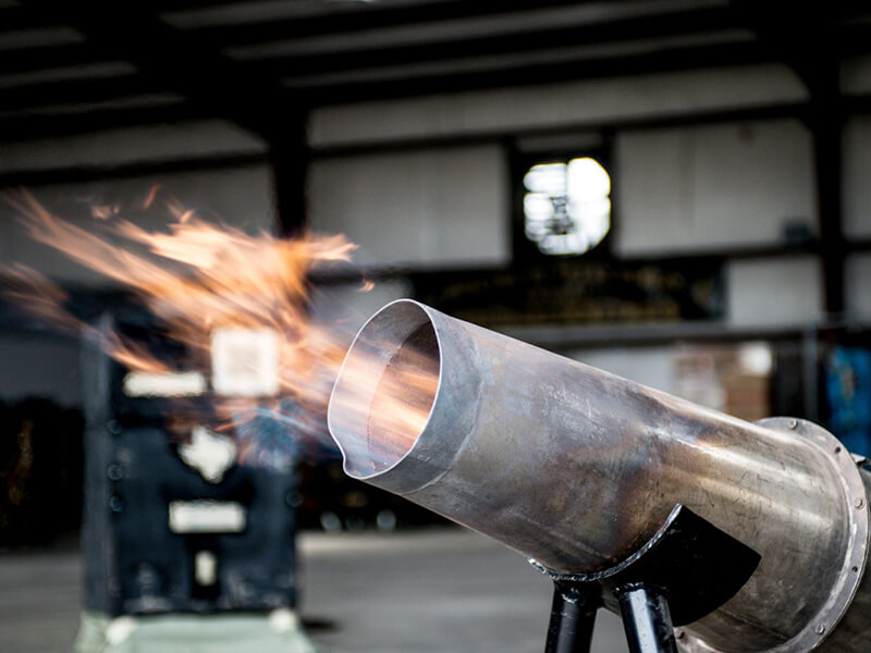
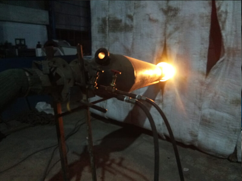
By external firing method large vessel seam LSR operation will be carried out by applying heat under controlled conditions using HAL high-velocity fuel-fired burners inserted via suitable openings into the temporary furnace and the products of combustion exhausted through suitable openings to the top of the furnace with dampers arrangement.
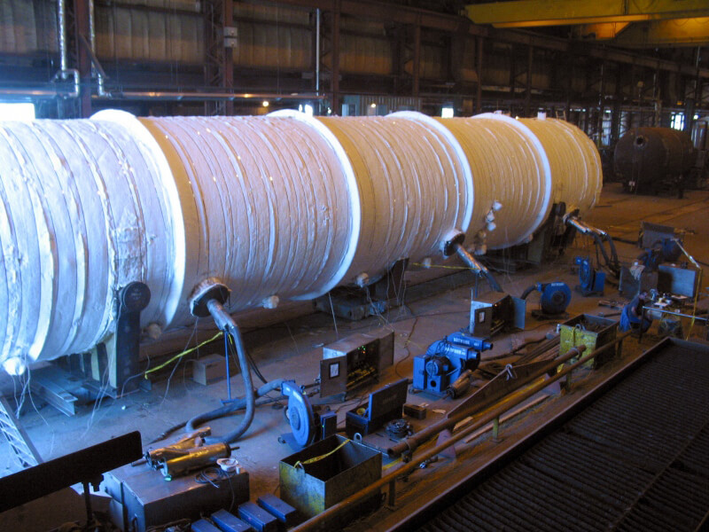
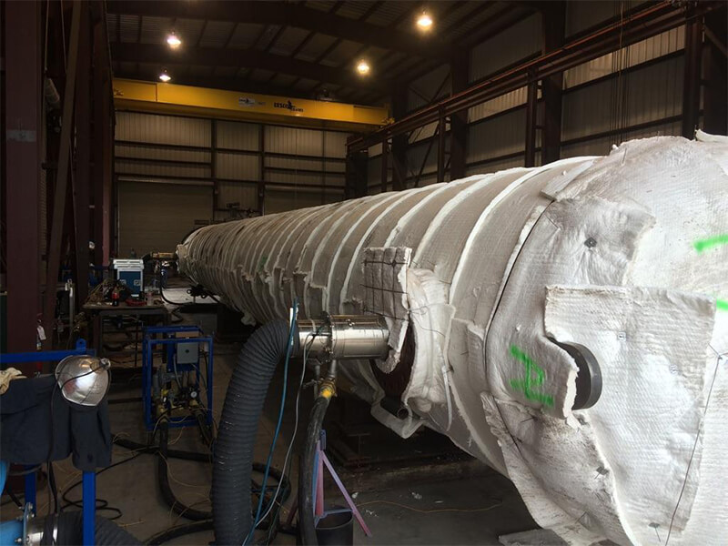
A large variety of Tanks, LPG Bullets, Pressure Vessels, Spheres and welded fabrications structures can be subjected to Post Weld Heat Treatment by utilizing the” HAL High-Velocity Burners. Temporary furnace can be built around the items to be treated or insulation can be applied directly to the outer surface and the item turned into its own furnace. The temperature uniformity that can be achieved by this method ensures that even the tightest standards and specifications are comfortably satisfied. The method used to heat treatment would be by means of a high-velocity burner inserted into the vessels by means of suitable man way Throughout the heating and cooling cycle the expansion and contraction of the vessels must be closely monitored and controlled to avoid any distortion of the structure.by means of suitable man way Throughout the heating and cooling cycle the expansion and contraction of the vessels must be closely monitored and controlled to avoid any distortion of the structure.
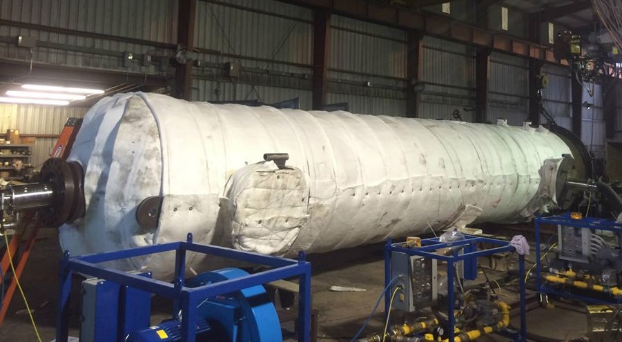
The heat treatment specifications and temperature constraints as per ASME SEC VIII Div1 2013 Edition will be applicable for entire Storage Vessel during the stress relieving operation. The Storage Vessel should have provision to enable free expansion & contraction of the vessel. The vessel shall be placed on a platform 500 mm above the foundation or shall be placed on the ground level (uniform flat surface). Uniform flat surface is very essential to ensure smooth expansion/contraction of the tank during heating/cooling. For 5 mtrs. Ø x 7 mtrs. ht. and 6 mtrs. Ø x 7.2 mtrs. ht The tanks shall be supported with minimum 10” Ø with 03 nos. radial supports. For 8 mtrs. Ø x 11.6 mtrs. ht. tank only The tanks shall be supported with minimum 12” Ø with 04 nos. radial supports, and External Stiffener for the Top Shells Coarse during the PWHT Operations as directed by our Supervisor. The tank is insulated with 100 mm thick ceramic wool insulation material having a density of 128 kg/m3 on its exterior surface. Before final placement of the tank either on platform/supports, 1 layer of ceramic wool shall be laid on ground/support, so that the base of the tank rests on the insulated ground/support. The high velocity burner with angled/straight cones will be inserted from the bottom manhole/nozzle opening. The products of combustion are exhausted through nozzles. The burner position across the tanks is such that circular of hot flue gases is created inside the tank, which ensures excellent temperature uniformity across the tank. The high velocity of the burner produces a scrubbing action on the shell surface, increasing the temperature uniformity. Care is taken to ensure that there is no flame impingement on any part of the tank.
The high-velocity burner will be controlled manually by continuous monitoring of temperature recorder. Control of temperature will be done by manual adjustment of Oil flow/pressure and by butterfly valves of blower (combustion air). The turndown ratio of the high-velocity burner is to the tune of 50:1 that gives high degree of control at all stages of firing. As the primary flame of the burner is enclosed in the main combustion chamber, at no time, the flame impinges on the vessel surface, totally avoiding hot spots. Exhaust gases will be taken out from the top manway & through other nozzle openings at the top. Calibrated thermocouples will be located at suitable locations as per the code requirement & connected to the multipoint calibrated ‘K’ type temperature recorder through colour-coded compensating cables. The thermocouples to be attached to the shell with the help of T/c.’s nut are from the Roll of 100 meters which is calibrated per 100 meters roll. Temperature will be monitored & recorded at regular intervals of time & the heat treatment cycle will be controlled accordingly. After completion of heat treatment cycle, duly certified time –temperature chart will be submitted to the client, signed and approved by DDB by IBR.