


 APPROVED
 - Home
- About Us
- Inspection Services
- Conventional Non-Destructive Testing
- Ultrasonic Weld Scan
- Ultrasonic Thickness Gauging
- Eddy Current Testing
- Radiography Testing
- Liquid Penetrant Testing
- View More
The use of NDT AND PWHT Solutions, high-velocity burners is an effective method of curing and drying out moisture from refractory materials in the startup process. Working under carefully controlled conditions, we can eliminate the risk of damage that can be caused by spalling and thereby extend the life of the refractory.
By external firing method large vessel seam LSR operation will be carried out by applying heat under controlled conditions using HAL high-velocity fuel-fired burners inserted via suitable openings into the temporary furnace and the products of combustion exhausted through suitable openings to the top of the furnace with dampers arrangement.
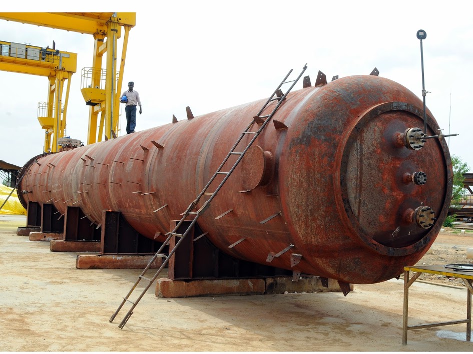
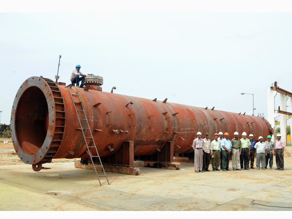
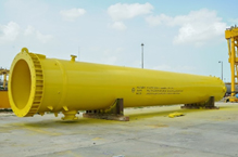
A large variety of Tanks, LPG Bullets, Pressure Vessels, Spheres and welded fabrications structures can be subjected to Post Weld Heat Treatment by utilizing the” HAL High-Velocity Burners. Temporary furnace can be built around the items to be treated or insulation can be applied directly to the outer surface and the item turned into its own furnace. The temperature uniformity that can be achieved by this method ensures that even the tightest standards and specifications are comfortably satisfied. The method used to heat treatment would be by means of a high velocity burner inserted into the vessels by means of suitable man way Throughout the heating and cooling cycle the expansion and contraction of the vessels must be closely monitored and controlled to avoid any distortion of the structure.by means of suitable man way Throughout the heating and cooling cycle the expansion and contraction of the vessels must be closely monitored and controlled to avoid any distortion of the structure.
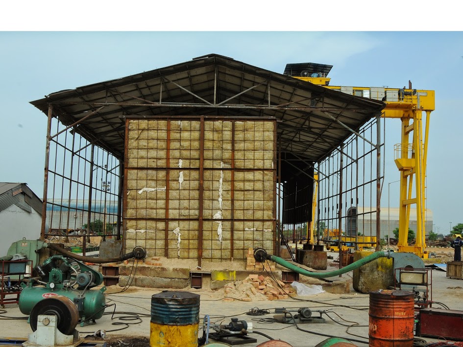
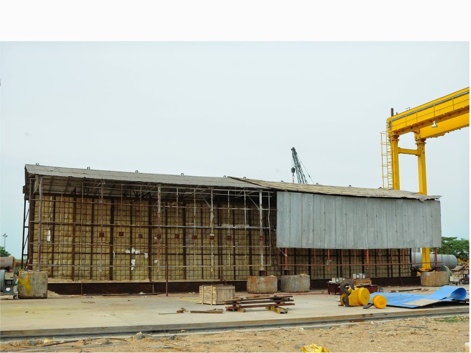
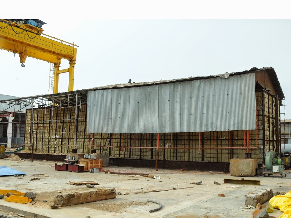
We propose that a temporary furnace to be fabricated of Scaffolding pipes or MS channel/flats/angles to be erectfed at site to carry out the stress-relieving cycles. The furnace walls and roof will be insulated with one layer of 100 mm thick 120 kg/m3 LRB mattresses. The hearth shall be covered with 150 mm thk sand.
We propose that the exchangers will be loaded in furnace from top of the furnace. The Exchangers should have provision to enable free expansion of contribution of the exchanger. The Exchangers shall be placed on a platform or placed on the ground (Uniform Flat surface) to ensure smooth Expansion/contraction of the exchangers during heating /cooling.
The high velocity burner will be inserted from the opening in the sidewalls of the furnace. The burner position is such that circular flow of hot fuel gases is created inside the furnace, which ensures excellent temperature uniformity inside the temporary furnace. The high velocity of the burner produces a scrubbing action on the shell surface, increasing the temperature uniformity. Care is taken to ensure that there is no flame impingement on any part of the vessel or section inside the temporary furnace.
The high-velocity burner will be controlled manually by continuous monitoring of temperature recorder. Control of temperature will be done by manual adjustment of oil flow/pressure and by butterfly valves of blower (combustion air). The turndown ratio of the high velocity burner is to the tune of 20:1, which gives high degree of control at all stages of firing. As the primary flame of the burner is enclosed in the main combustion chamber, at no time, the flame impinges on the vessel surface, totally avoiding hot spots. Exhaust gases will be taken out from suitable openings provided in the roof of the furnace.
Calibrated thermocouple will be installed at suitable locations as per the code requirement connected to the multipoint calibrated ‘K’ type temperature recorder through colour coded compensating cables.
Temporary furnace erected of scaffolding material will be externally insulated with one layer of 100 mm thick LRB insulation, 120 kg/m3 density. The insulation mats will be enmeshed in chicken wire mesh. All the gaps between the insulation mats will be plugged with insulation prior to each charge of temporary furnace. The hearth of furnace shall be prepared of sand at site.
Thermocouple will be located over the length as per specifications. Thermocouples will be attached to the grider either with thermocouple nuts or with thermocouple attachment unit.
2 nos. High-Velocity burner (HSD fired) will be inserted from openings mad on the sidewalls of the temporary furnace.
The combustion equipment will comprise of burner, blower, pilot burner with spark ignition system, flexible hoses and control station. Heat cycle profile control will be achieved by controlling fuel flow and combustion airflow through regulating valves.
The thermocouple wire (T/C) will be of CR-A1 i.e. K type of 21/22 SWG, which will be attached to the shell either by thermocouple attachment unit or by thermocouple nuts.
Copper constantan compensating cables will be used for the connection between T/C wire and temperature recorder. The copper lead (+ve) will be connected to the Cr-A1 conductor (non-magnetic) and the constantan lead (-ve) lead to the Ni-A1 conductor (magnetic).
Each thermocouple will be connected to a calibrated continuously monitoring temperature recorder, thus providing temperature chart printout giving information on temperature variations and trends during the SR cycle.
The chart will be presented as a record of the heat treatment cycle. The recorder will be adjusted from a range of 0˚C-1200˚C with appropriate chart speed.
Latest calibration certificate of the thermocouple wire & temperature recorder will be submitted before start of the SR cycle.
The thermocouple recorder will be calibrated immediately before the first heat treatment cycle and then at intervals not exceeding 6 months.